Using Meters and Sources
star
star
star
star
star
Last updated over 4 years ago
29 Nsɛmmisa
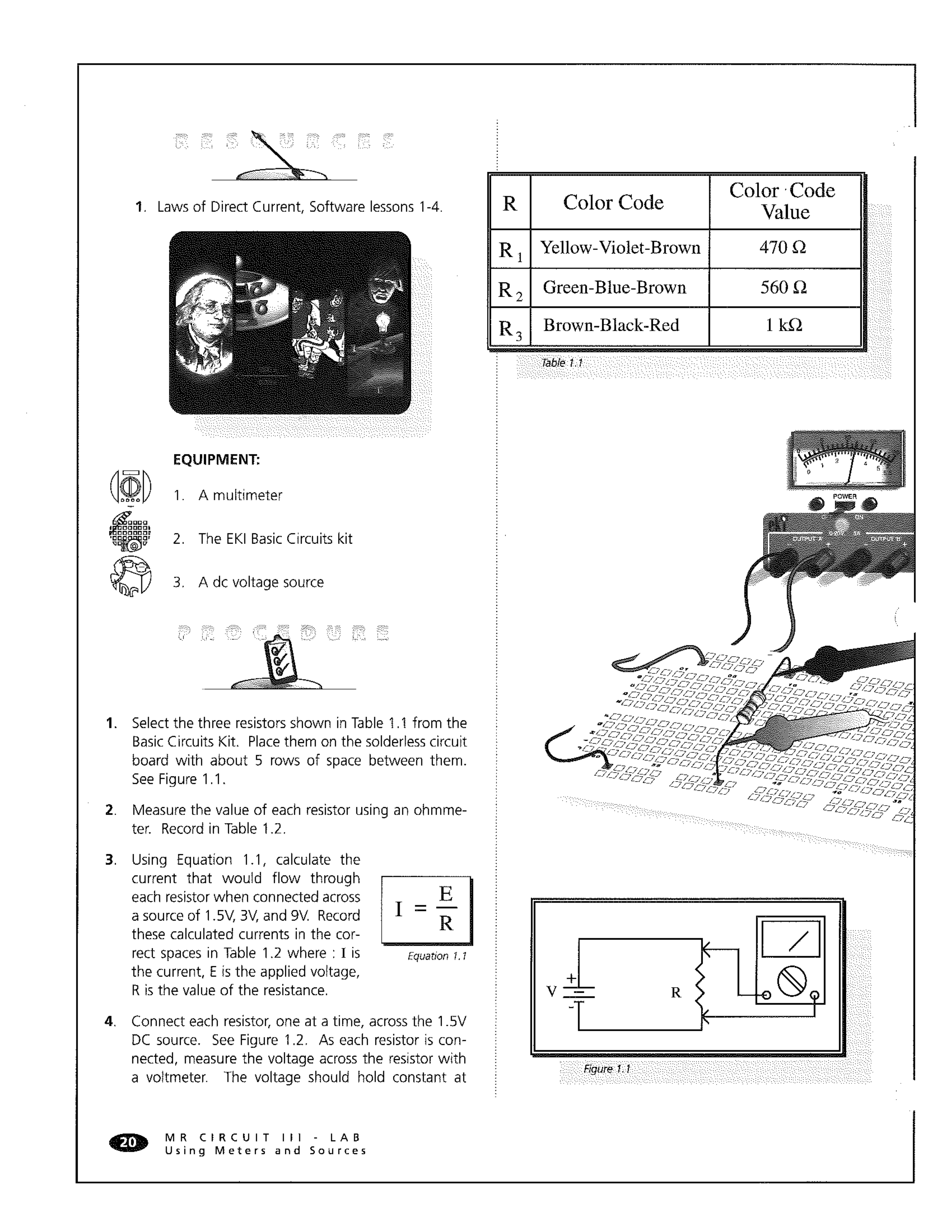
It is not necessary to measure the individual resistance of each resistor in a simulation. They should be what they say they are!
Read the directions on this page and fill in the requested calculations and measurements using the provided fields below.
Do the Ohm's Law work on a peice of scrap paper and upload a picture your work with your answer for full credit.
What is the calculated current for R1 with 1.5 V?
What is the calculated current for R2 with 1.5 V?
What is the calculated current for R3 with 1.5 V?
What is the calculated current for R1 with 3 V?
What is the calculated current for R2 with 3 V?
What is the calculated current for R3 with 3 V?
What is the calculated current for R1 with 9 V?
What is the calculated current for R2 with 9 V?
What is the calculated current for R3 with 9 V?
What is the value of R1? Always write your answer in engineering notation with base units. Here's the Ω so you can copy and paste it as needed.
What is the value of R2?
What is the value of R3?
Use TinkerCAD to measure current R1 with 1.5 V. Upload an image of the TinkerCAD circuit with this measurement.
Use TinkerCAD to measure current R2 with 1.5 V. Upload an image of the TinkerCAD circuit with this measurement.
Use TinkerCAD to measure current R3 with 1.5 V. Upload an image of the TinkerCAD circuit with this measurement.
Use TinkerCAD to measure voltage at R3 with 1.5 V. Upload an image of the TinkerCAD circuit with this measurement.
Use TinkerCAD to measure voltage at R2 with 1.5 V. Upload an image of the TinkerCAD circuit with this measurement.
Use TinkerCAD to measure voltage at R3 with 1.5 V. Upload an image of the TinkerCAD circuit with this measurement.
Use TinkerCAD to measure current at R1 with 3 V. Upload an image of the TinkerCAD circuit with this measurement.
Use TinkerCAD to measure current at R2 with 3 V. Upload an image of the TinkerCAD circuit with this measurement.
Use TinkerCAD to measure current at R3 with 3 V. Upload an image of the TinkerCAD circuit with this measurement.
I'd have you keep measuring voltage but I feel like you should be picking up on a trend at this point. What do you think the measured voltage is for each resistor and why? Look back at what you measured for 1.5 V.
Use TinkerCAD to measure current at R1 with 9 V. Upload an image of the TinkerCAD circuit with this measurement.
Use TinkerCAD to measure current at R2 with 9 V. Upload an image of the TinkerCAD circuit with this measurement.
Use TinkerCAD to measure current at R3 with 9 V. Upload an image of the TinkerCAD circuit with this measurement.
You would write the same answer here as you did for number 22.
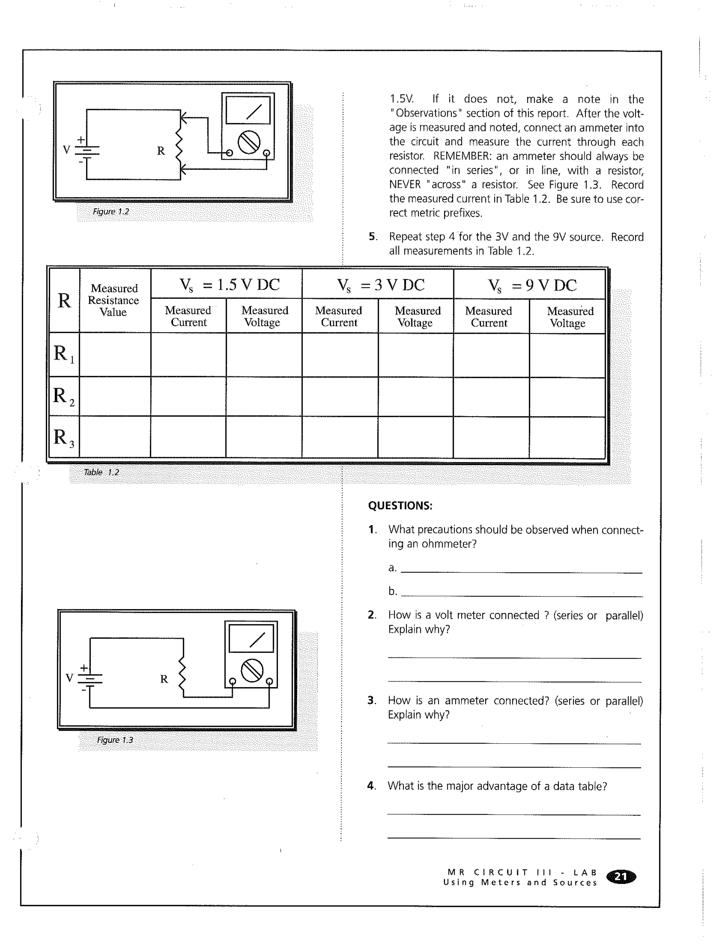
What precautions for setup should be observed when connecting an ohmmeter to measure resistance in a circuit?
How is a volt meter connected to measure voltage?
How is a ammeter connected to measure voltage?