Log in
Sign up for FREE
arrow_back
Library

Unit 6 Performance Task

star
star
star
star
star
Last updated about 4 years ago
12 questions
0
4
4
4
4
4
4
7
1
4
2
2
Equations

Images

To take photos, click on the image button in the show your work section as shown above. Click take photo to take a picture of your lab set ups.


To insert screenshots, on your key board click Ctrl + Shift + Show Windows button as shown above. Crop as desired then click capture. When you click capture it copies the screenshot.


Go back into the show your work section and on your keyboard click Ctrl + V to paste the screenshot.
Question 1
1.

Write the name(s) of your partner(s) below.

Challenge 1: Circuits

All questions in this challenge relate to each other.
Question 2
2.

With the materials at your station, build a closed circuit with 2 light bulbs connected in parallel. Take a picture of your circuit with all the lights on and insert the image in the Lab Circuit box.

Go HERE. Click on Intro. Build the circuit you created with the materials in the simulation. Take a screenshot of your circuit with all the lights on and paste the image in the Simulated Circuit box.

Question 3
3.

The total resistance in the circuit you built is approximately 1.2 Ω and the voltage of the battery is 1.5 V. Determine the current moving through the battery.
  • Show your work in the show your work section.
  • Type your numerical answer and units in the numeric section.

Challenge 2: Magnetism

All questions in this challenge relate to each other.
Question 4
4.

Take one bar magnet out and place it on the table. Use the compass to determine the North and South pole of the bar magnet.

In the show your work section:
  • Label the North and South pole on the bar magnet.
  • Draw how the north compass needle would point in the circles near the bar magnet.

In the written response section:
  • Explain how you were able to determine the North and South pole.
  • Explain the scientific reasoning behind your choice.

Question 5
5.

Suspend two paperclips tip to tip without interlocking them onto the red end of your bar magnet as shown in the show your work section. Determine the correct induced pole structure for each paper clip.

In the show your work section:
  • Label the bar magnet with an N or S at each pole.
  • Write N or S at each pole of the paper clips.
  • In the zoomed in view, show how the domains would look for the paper clip.
In the written response section:
  • Explain how the paper clips are able to be suspended from the bar magnet. Discuss domains in your explanation.

Question 6
6.

Label the bar magnet with an N or S at each pole. Draw the magnetic field lines around the bar magnet. Make sure to show correct field line direction and show relative field strength by changing the field line density.

Challenge 3: Electromagnetism

All questions in this challenge relate to each other.
Question 7
7.

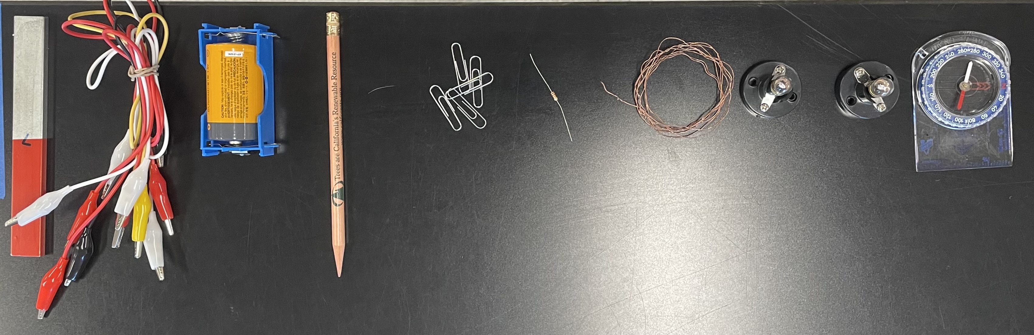
Build the strongest electromagnet you can with the Material List below. Count the amount of coils you add to your solenoid. Not all materials have to be used but you can use any of the materials given.

Material List:
  • Iron Nail Core
  • Pencil Core
  • Copper Wire
  • Resistor
  • 1.5 V D cell battery
  • 2 wires with alligator clips
In the show your work section:
  • Take a picture of your electromagnet. Insert the image in the Lab Electromagnet box.
  • Hand draw a picture of the electromagnet you built in the Picture Representation box so Ms. Hall can clearly see what you built.
  • Label all your components that you used from the material section that you used. Label the amount of coil turns you added.
In the written response section:
Using the formula for the magnetic field, explain your electromagnet build choices. You can simply state how the formula supports the build choices you made. The build choices you must discuss are:
  • Core choice (Iron Nail / Pencil / Air)
  • Coil Turns (how many coils you added)
  • Resistance (adding a resistor / excluding a resistor)

Question 8
8.

Click HERE. You can change the coil turn density (coils per unit length) and the current and measure how the magnetic field changes. Use the simulation to determine the relationship between coil turn density and the magnetic field around the coil. If the simulation is not working, Ms. Hall has provided you with a printed data table.

In the google sheet you have open, create a scatter plot to determine the relationship between coil turn density and the magnetic field around the coil. Plot at least 4 data points. Make sure your graph has a chart title and axes titles. Add a trendline and an equation for the line of best fit.

In the show your work section:
  • Take a screenshot of your scatter plot and data table and insert the image.

Question 9
9.

Refer back to question 8. Choose the relationship between coil turn density and the mangnetic field.

Question 10
10.

Solenoids are made on an industrial scale by wrapping a copper wire into a coil around a ferrite core. Ferrite is a blend of iron oxide and a multitude of other metals that has relative permeability of 1500. The solenoid is 0.05 meters in length and has 50 coil turns around it. There is 10 Amps of current moving through the solenoid. Determine the magnetic field produced by this solenoid.

  • Show your work in the show your work section.
  • Type your numerical answer and units into the numeric section.

Question 11
11.

Look at the solenoid below. Determine where the North and South Pole are located on your solenoid.

Question 12
12.

Current is moving through the closed circuit as shown below. Determine the direction of the magnetic field lines at Location A. A zoomed in view of the wire and Location A is shown above. Location A is on top of the wire as shown.

Before clicking submit:

  • Check the rubric for every question
  • Call Ms. Hall over to review your responses
  • Clean up your lab staion as shown in the image to the right