Go onto Using https://logic.ly/demo/
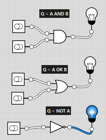
Try to replicate this image by dragging
"Toggle Switches"
"AND GATE"
"OR GATE"
"NOT GATE"
"Lightbulb"
together.
What is a Logic Gate?
A logic gate is a basic building block of electronic circuits. It takes one or more input signals and produces an output signal based on a specific rule.
Info:
Q doesn't really mean anything. It is just the system.
"A", "B", "C" refers to an individual "Toggle Switch"
AND : is on, when both inputs are on (1)
OR : is on when at least one input is on (1)
NOT : Flips the input (e.g. 1 to 0)
0 means off
1 means on
"AND" Gate output On/True (1) when ....
Guided Practice: Using https://logic.ly/demo/
Create a logic gate system that is:
Q = NOT (A AND B)
(Only has an output if both A and B are 0)
Task A – Using https://logic.ly/demo/
Create a logic gate system that is:
Q = NOT (A OR B)
(Only has an output if both A and B are 0)
Crate a logic gate system that is:
Q = (A OR B) AND C
(Only has an output if C is 1 and at least one of A or B are 1)
Extension:
Q = (A AND NOT B) AND C
Extension:
Q = NOT A AND (B OR C)
Extension:
Q = (A AND B) AND (NOT C AND D)
Now let's try filling in the "Truth Table".
Copy the Logic Gates diagram for each question and work out when the light bulb turns on or off
Remember, each letter is just one of the "toggle switches"
0 is off
1 is on
Task B –
Using the diagrams of logic gates complete the table below...
Task B –
Using the diagrams of logic gates complete the table below...
Task B –
Using the diagrams of logic gates complete the table below...
Task B –
Using the diagrams of logic gates complete the table below...